
SolarEdge
This integration guide is compatible with the following SolarEdge StorEdge® products:
StorEdge® Single Phase Inverter
StorEdge® Three Phase Inverter
SolarEdge Single Phase Inverter + StorEdge® Interface
SolarEdge Single Phase Inverter + SolarEdge Home Battery 400V
Depending on their type, SolarEdge devices may be configured in either of the two ways:
Using SetApp
Using the LCD (Firmware version 3.xxxx and above only)
1. Modbus support
The following types of communication can be used to connect the SolarEdge devices to the FlexiObox.
Option 1) Ethernet - Connect the inverter to the FlexiObox using the local network (Modbus TCP).
Option 2) RS485 - Connect the inverter to the FlexiObox using the RS485 dongle (Modbus RTU).
By default the modbus communication is disabled and needs to be enabled through the SolarEdge SetApp. See section 3 or 4 on how to enable it.
2. Wiring
You can skip this chapter if the inverter is already connected to the local network and will communicate with FlexIo Box through Ethernet. Otherwise follow the steps bellow.
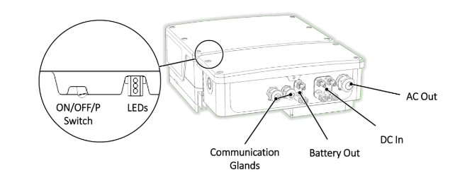
2.1. Remove the inverter cover
Switch the inverter ON/OFF/P switch to OFF. Wait 5 minutes for the capacitors to discharge.
Turn the Connection Unit (if applicable) to OFF.
Disconnect the AC to the inverter by turning OFF the circuit breakers on the distribution panel.
Open the Allen screws of the inverter cover and carefully pull the cover horizontally before lowering it.
2.2 - Option 1) Connect to FlexIo using the local network
Remove the inverter cover as described in section 2.1
Open the communication gland #1.
Remove the plastic seal from one of the large openings.
Remove the rubber fitting from the gland and insert the CAT5/6 cable through the gland and through the gland opening in the inverter.
Insert the ethernet cable through the opening in the Connection Unit towards the communication board.
Push the cable into the cut opening of the rubber fitting.
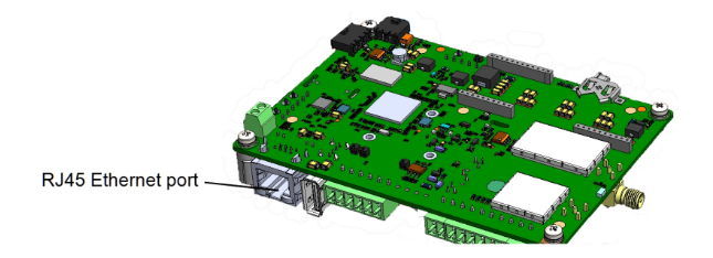
Connect one end of the ethernet the cable to the RJ45 plug on the inverter’s communication board.
Connect the other end of the ethernet cable to the RJ45 port of the Ethernet switch or router.
Warning:
Both the inverter and the FlexIo box must be in the same local network.
2.3 - Option 2) Connect to FlexIo using RS485
Remove the inverter cover as described in section 2.1
Remove the seal from one of the openings in communication gland and insert the wire through the opening.
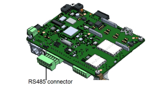
Pull out the RS485 terminal block connector from the communications board, as shown below.
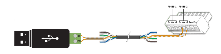
Connect the RS485-2 terminals to the FlexIo RS485 dongle terminals. Use the orange/white conductor to connect the “A” terminals, and the orange conductor to connect the “B” terminals.
Note
RS485-1 port can be used if the RS485-2 port is not available.
3. Enable Modbus - SetApp Inverters
Install the SolarEdge SetApp Application if not already.
Login with your SolarEdge partner account
Connect your phone to the inverter by scanning the label QR code.
Option 1) Enable Modbus TCP if using the local network for connection. Skip to step 5 if using RS485.
Select Communication -> Modbus TCP -> Enable
Select Communication -> Modbus TCP -> TCP Port -> 1502
Option 2) Enable Modbus RTU. Skip this step if using Modbus TCP.
Select Communication -> RS485-2 Conf -> Protocol -> SunSpec
Select Communication -> RS485-2 Conf -> Device ID -> 1
Note:
RS485-1 port can be used if the RS485-2 port is not available.
4. Enable Modbus - Non SetApp Inverters (LCD)
Option 1) Enable Modbus TCP if using the local network for connection. Skip to step 2 if using RS485.
Select Communication -> LAN Conf -> Modbus TCP -> Enable
Select Communication -> Modbus TCP -> TCP Port -> 1502
Option 2) Enable Modbus RTU. Skip this step if using Modbus TCP.
Select Communication -> Server -> Select any server connection, except for RS485 (if the inverter is not connected to the SolarEdge monitoring platform, select None.)
Select Communication -> RS485-1 Conf -> Device Type -> Non-SE Logger
Select Communication -> RS485-1 Conf -> Protocol -> SunSpec
Select Communication -> RS485-1 Conf -> Device ID -> 1
Note:
RS485-1 port can be used if the RS485-2 port is not available.