
GoodWe Energy Storage Inverters
For the inverter compatibility list, see FlexiO compatible inverters & charging stations.
In this section you’ll find instructions on how to integrate FlexiO with Goodwe Energy Storage Inverters.
This guideline provides instructions for connecting the FlexiObox and configuring FlexiO.
For detailed hardware instructions, see the individual battery and inverter manuals of the manufacturer.
Attentention when you adapt standard settings in Goodwe inverter:
-
Goodwe uses the term "Max discharge battery", which is set to 90% by default. This means the battery can discharge up to 90%, so the min SoC is then 10%.
-
Changes made in the SEMS portal are not always applied, which makes it appear that the setting has been changed while locally it still remains at the configured value.
It's important to know that FlexiO always reads the local value via the modbus connection. It makes sense for FlexiO to adopt this value, otherwise significant control errors could occur that would be detrimental to your user. So if you notice that the min SoC setting jumps from the default setting of 10% to a different value, this means it's actually configured that way in the inverter. This may be intentional if the battery is also used for backup purposes.
1. Modbus Support
Overview of the different connections:
|
Reference |
GoodWe model |
Communication port connector type |
Necessary accessoiries |
|---|---|---|---|
|
Standard GoodWe inverters |
RJ45 |
||
|
3-phase GoodWe inverters |
Proprietary connector |
|
Some inverters have different cabling, depending on the type of inverter
1.1 Modbus for standard GoodWe inverters
To connect a standard GoodWe inverter, combine the 2 following items:
-
-
Connect one side to the GoodWe Black Dongle [LMGS] female RJ45
-
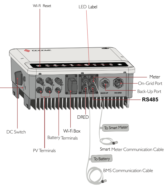
Connect the other side to the RS485/EMS port of the standard GoodWe inverter
-
-
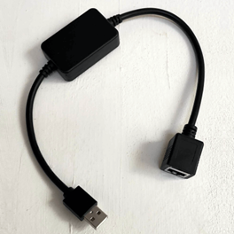
GoodWe Black Dongle [LMGS]: plug the USB connector into one of the 4 FlexiObox USB ports
The S/FTP cable [LSF2] is sold with a length of 2 meters. Unlike UTP, S/FTP is a shielded network cable (Cat6) which ensures high quality for this type of serial connections.
Alternatively any qualitative S/FTP (Cat6 or higher) cable can be used.
Related: Where to order these products.
1.2 Modbus for 3-phase GoodWe inverters
To connect a 3-phase GoodWe inverter, combine the 3 following items:
(not sold by LIFEPOWR)
-
-
Remove the RJ45 connector on one side and strip the cable to uncover the 8 coloured (twisted pair) cables.
-
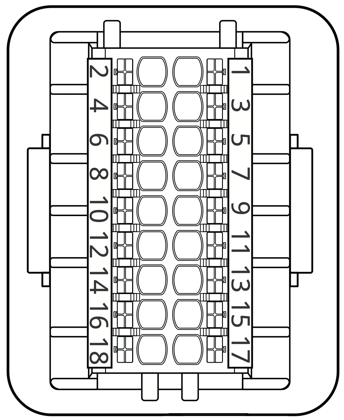
Connect following coloured cables to the proprietary connector:
-
Both Orange/White & Green/White cables to position 1
-
Both Orange & Green cables to position 2
Proprietary connector
-
-
Tip: use a heat shrink to cover the internal S/FTP cables.
-
Plug the proprietary connector into the 3-phase GoodWe inverter
-
Connect the other side to the GoodWe Black Dongle [LMGS] female RJ45
-
Plug the GoodWe Black Dongle [LMGS] USB connector into one of the 4 FlexiObox USB ports
2. Goodwe Smart Meter installation
All GoodWe inverters have a build-in smartmeter to measure grid power.
This measurement is crucial for the inverter to function properly and being able to run the instalation in standalone modus (separate from FlexiO) which is a prerequisite before connecting and activating FlexiO.
In the event that a GM1000D Smartmeter is supplied with Retrofit inverters, there is a second current transformer (CT) that should be installed on the output (AC) of the PV inverter. See the figure below.
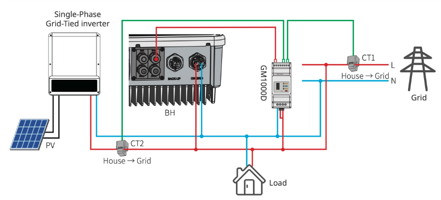
It is important to note the AC connection on the GM1000D where the L1 and L2 needs to be connected to Live.
If the GM1000D is installed with CT2 connected to the output of the PV inverter, InverterPVRetro should be selected in the Device Details under Retrofit PV Measurement.
3. Goodwe EZLink3000
-
Master/Slave Support: Via the EZLink3000 we now officially support Master/Slave configurations. This makes controlling complex systems with multiple inverters simpler and more efficient.
-
EZLink3000 Validation: Additionally, we have validated the compatibility of the EZLink3000 for systems with a single inverter.
These improvements are now available in both the Partner Portal and for end users.
Datasheet Goodwe EZLink3000: GW_Ezlink 3000_Datasheet-EN.pdf
4. Technical support
Visit the support page.